graph LR

    C1(Wall)
    C2(Wall)
    N[/Stage Network/]
    IN[/Internet/]
    H[(Helix Core)]

    subgraph VC [Volume Control]
        A[Workstation]
        A1[Editing Workstation]
        A2[DMX]
    end

    subgraph Wally [Wall Rack]
        E[Evertz]
        B1[Brompton]
        B2[Brompton]
        B3[Brompton]
        P[Wall Computer]
    end

    A1 <--> N
    A <--> N
    A2 <--> N
    P <--> N

    B1 -->|mCAST| C1
    B2 -->|mCAST| C2
    E -->|Genlock| B1
    E -->|Genlock| B2
    E -->|Genlock| B3
    E -->|Genlock| P
    N --> E

    P --> |DVI| B1
    P --> |DVI| B2
    P --> |DVI| B3

    N <--> IN
    N <--> H

    subgraph Camera [Camera\n Package]
        Cam[Camera]
        Mo[Mo-Sys]
    end

    E -->|Genlock| Cam
    Mo <--> N
    Cam -->|SDI| P
Note
Last built on: Last built on: format(Sys.Date(), '%Y-%m-%d')
Stage Setup
Note
Note: This is simply the craziest setup for control of the refresh rates I’ve ever seen. It’s a wonder it works at all. If you are in a panic, ask for help.
Time / frame synchronization on the stage computers and cameras is critical — and brutally inconvenient. There are multiple places the frame rates have to be set for a successful shoot.
The stage has two main systems — the Volume Control station(s) and the Rack. Volume Control (VC) is a separate workstation in the back of the stage that you use remotely to control the display computers in the Rack. Ideally you’d set the Rack up and then never touch it again. You’d do all your work from the Volume Control station which is synchronized with the Rack automatically using Helix.
We have been using Parsec to remote into the Rack, but it’s not ideal as it does a lot of magic behind the scenes1 that can mess up the display settings. We really need to make this complex task as simple and straightforward as possible. Ideally we should be using a wireless KVM switch to control the rack and we’re hoping to move in that direction soon.
As mentioned above, files and resources on the rack are synchronized by using Helix Core2. Helix is a version control system, like git, that allows you to check out files, work on them, and check them back in. It’s a bit like a shared Google Drive, but with more control and less convenience. The VP Template project should have all the Helix settings set up for you. If you need to do anything special, you can look at other documents here.
The stage setup is shown in the following figure:
This is correct as of Fall 2024
I’m certain all this will change over time as we dial in the setup. Come back here for more information as it evolves.
The figure below shows the Rack setup in more detail:
graph TD
    %% Subgraph for the Computer
    subgraph Computer [Wall Computer]
        subgraph NVIDIA
            A6000-1
            A6000-2
        end
        subgraph Windows
            A[UE]
            P[(Helix)]
            A <--> P
        end
        A --> NVIDIA
    end

    %% Subgraph for the Wall
    subgraph VP Wall
        B[Video Processors x 2 + 1 Spare]
        C(Wall Panels x 250)
    end

    NVIDIA -->|DVI| B
    B -->|Ethernet| C

    %% T[Genlock] --> |24Hz| A
    T[Genlock] --> |24Hz| B
    T --> |24Hz| NVIDIA
    T --> |24Hz| Windows
The Rack has dual NVIDIA A6000 cards that drive the wall using Mutiprocessing3. The cards share the work of computing the inner- and outer- frustum which is configured in the UE project. In short:
- Card 1 computes the inner frustum (camera view)
- Card 2 computes the outer frustum (background view)
- Card 1 composites the inner frustum over the outer frustum
- Card 2 delivers the video signal to the Brompton processors
- The Brompton processors drive the wall
It’s a little more detailed than that, you have to make sure nDisplay is configured correctly, and that the preset for the UE control panel are also set up right, but that’s the basic idea4.
The Importance of Synchronization
It is crucial that there is temporal synchronization between the cameras, the wall, and the computers. This is done by setting the frame rates of the cameras, the wall, and the computers to 24 Hz and using a House Clock that provides a genlock signal to the computers and cameras.5
Conventions
We use 24 fps for everything. The Evertz timecode generator (AKA the House Clock) is set and locked to 24 hz. We use the integer 24 fps, not 23.976 or 24.0001. If you are unsure what this means, ask an MPS student!
Avoiding the Wrath of those who Keep the Wall
It is entirely possible to change the frame rates of the House Clock (the Evertz) from the front panel or via a particular app. If you do this be warned that you can mess things up pretty badly for those who come after you. It’s best to leave the Evertz alone lest you incur the wrath of Those Who Keep the Wall.
We know there might be applications that require different frame rates and we can usually accommodate them. Unless you are 100 percent certain that you know what you are doing, do not change the frame rate of the Evertz.
The Volume Control Doesn’t Matter
You can drive the displays of the Volume Control stations at any rate you please. They have no effect on the project, wall, cameras or anything in the Rack.
1/24
One twenty-forth of a second is 41.66666666666667 ms. This is the time it takes for a frame to be displayed at 24 fps. Note that it is a repeating number, so it’s not possible to display a frame for exactly 41.66666666666667 milliseconds. The computer will round up or down to the nearest whole number, which is 42 ms. We’ll have to live with that little bit of error, but, beware because it builds up. If you display a frame for exactly 42 ms you’ll be off by 1 frame every 40 seconds. That’s one of the stranger problems that might bite you in the butt, especially if you’re speeding for very long periods of time.
We should probably add other conventions here too, like base wall intensity, resolution, etc.
Places for Frame Rate Settings
There are multiple places to set the frame rates, here we get to see them grouped by the subsystem they live in:
graph TD
    subgraph Camera Package
        A[Camera]
        B[Mo-sys]
    end

    subgraph Helix
        C[UE Project]
    end


    subgraph Rack
        D[Evertz]
        subgraph Windows 11
            E[Windows Display Settings]
            F[NVIDIA Control Panel]
        end
        G[Brompton Processors]
    end
Cameras
Not seen here are the cameras used to shoot the wall. These too must be set at 24 fps6.
Right now, the only camera we have that has build-in genlock is the Black Magic Ursa. The ARRI supports genlock, but we don’t have the hardware enabled to do it. Again, the plans are to get the ARRI set up for genlock, but it’s not there yet.
Camera Menu Screen Shots
There should be screenshots of the camera menu settings here.
UE Project
The Unreal project’s framerate has to be set for the wall refresh rate. This is done in the project settings.
Figure Needed
Caution: The UE project settings are not the same as the Windows display settings. They have to be set separately.
Processor Rack Computer
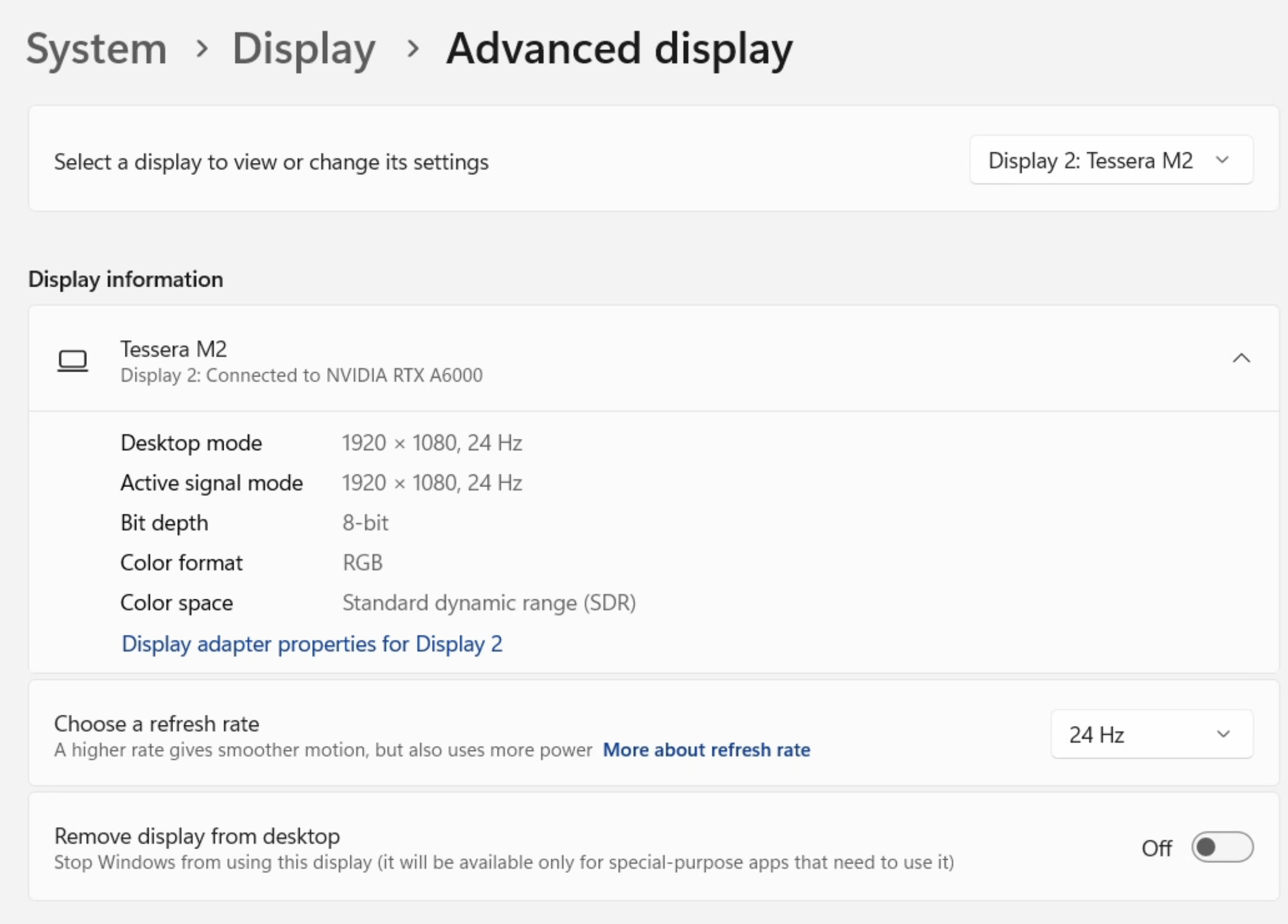
Here’s where stuff goes off the rails. There are multiple places to set the frame rates. Firstly, there’s Windows 11 control panel, System > Display and you know we’re in trouble since we have to go to the Advanced display settings to start with.
Windows Display Settings
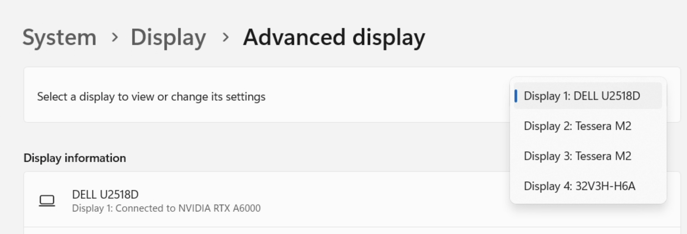
Notice the four displays listed. The two we care about are the Tessera M2 processor displays. These are the ones that drive the wall.
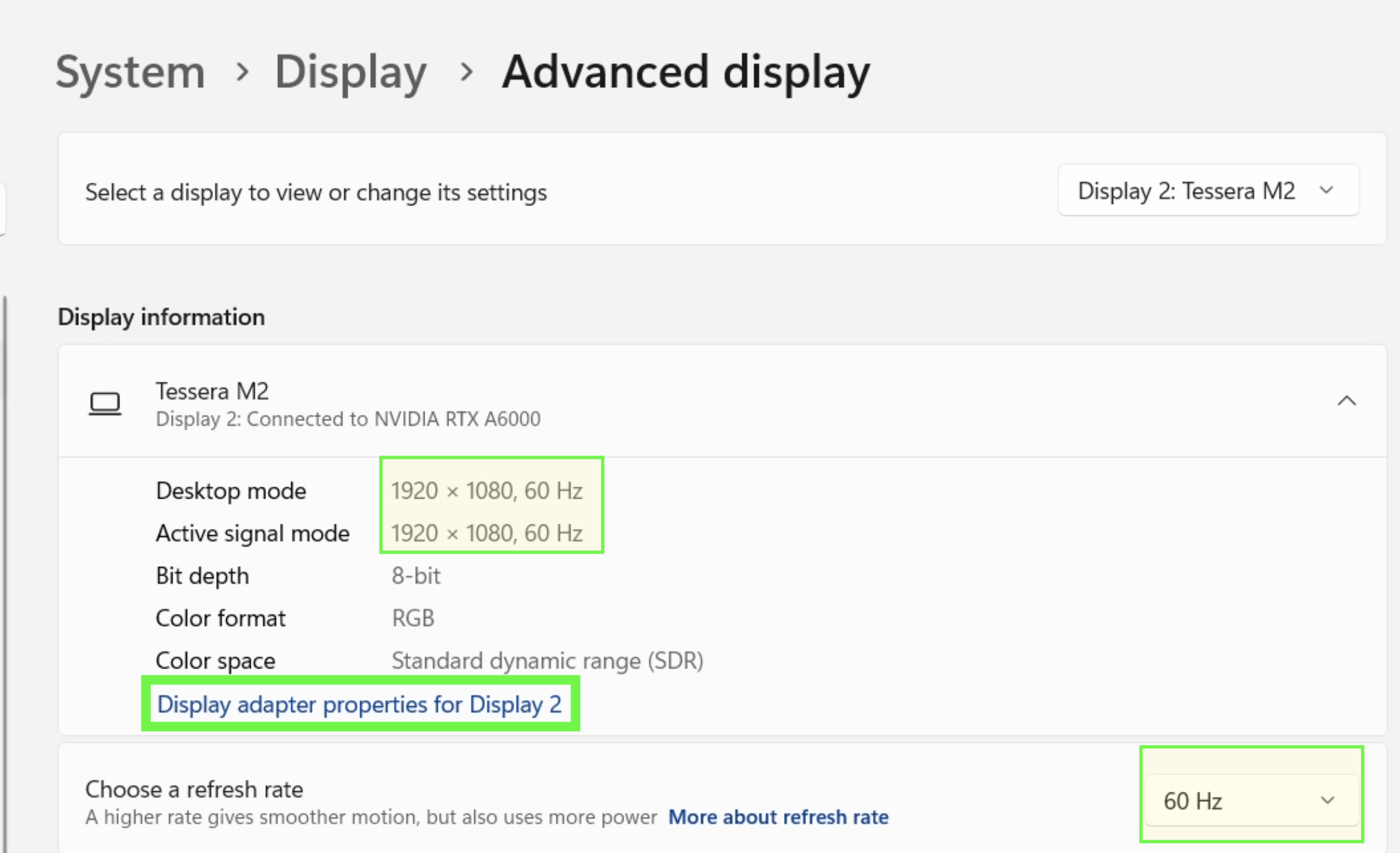
You’ll notice that, much to my chagrin, Figure 5 shows the refresh rate is set to 60 Hz. This is not what we want. We want 24 Hz.
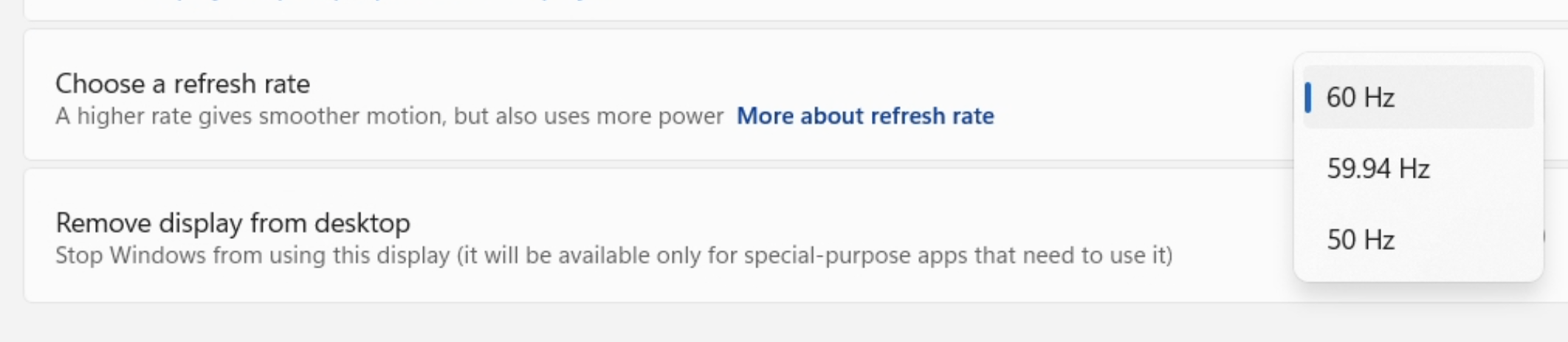
Unfortunately, Windows does not recognize the 24 Hz setting. It’s not in the list. The display is capable of 24 Hz however, and I have created an entry in the Advanced Display Settings for it.7 We need to go to the Display adapter properties for Display X (Green box in Figure 5) to make those changes.
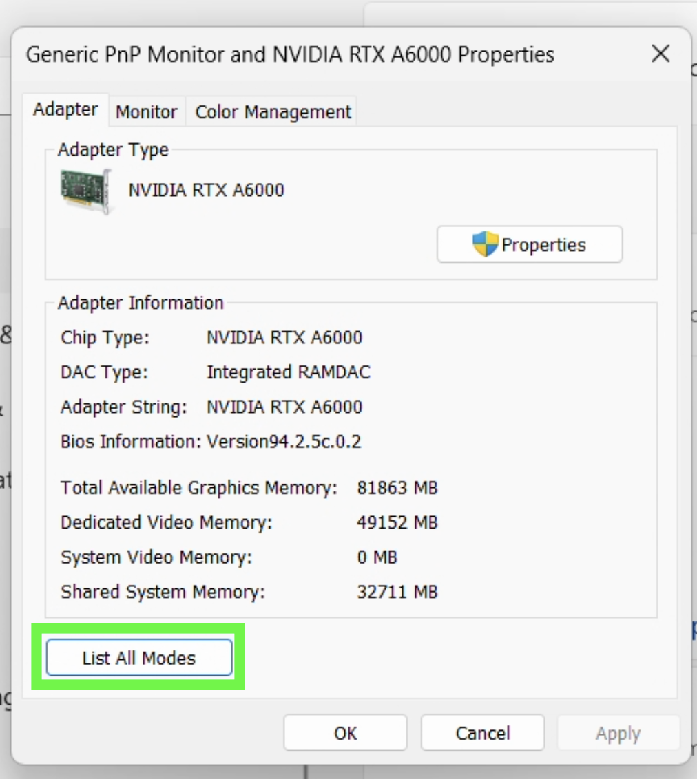
The List All Modes button will show you all the modes the display is capable of. You can select the 24 Hz mode from there, it’s at the top in a specially curated ‘custom’ section.8
You should select 1920 by 1080, True Color (32 bit), 24 Hertz from the list. This will set the display to 24 Hz, probably.
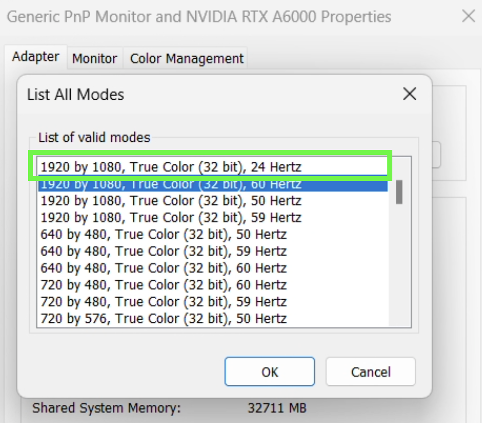
Now, go back to the second Tessera Display and make sure the same settings are applied.
If you have done this correctly you should take a break and congratulate yourself. You should probably take a nap or something because you’re going to need it to get through the rest of this.
NVIDIA Control Panel
The NVIDIA Control Panel sits between Windows and the display output. You’re in a circumstance where you have to set the refresh rate in four places. The NVIDIA Control Panel is the third place.
I’m so sorry for this.
The NVIDIA Control Panel looks like this:
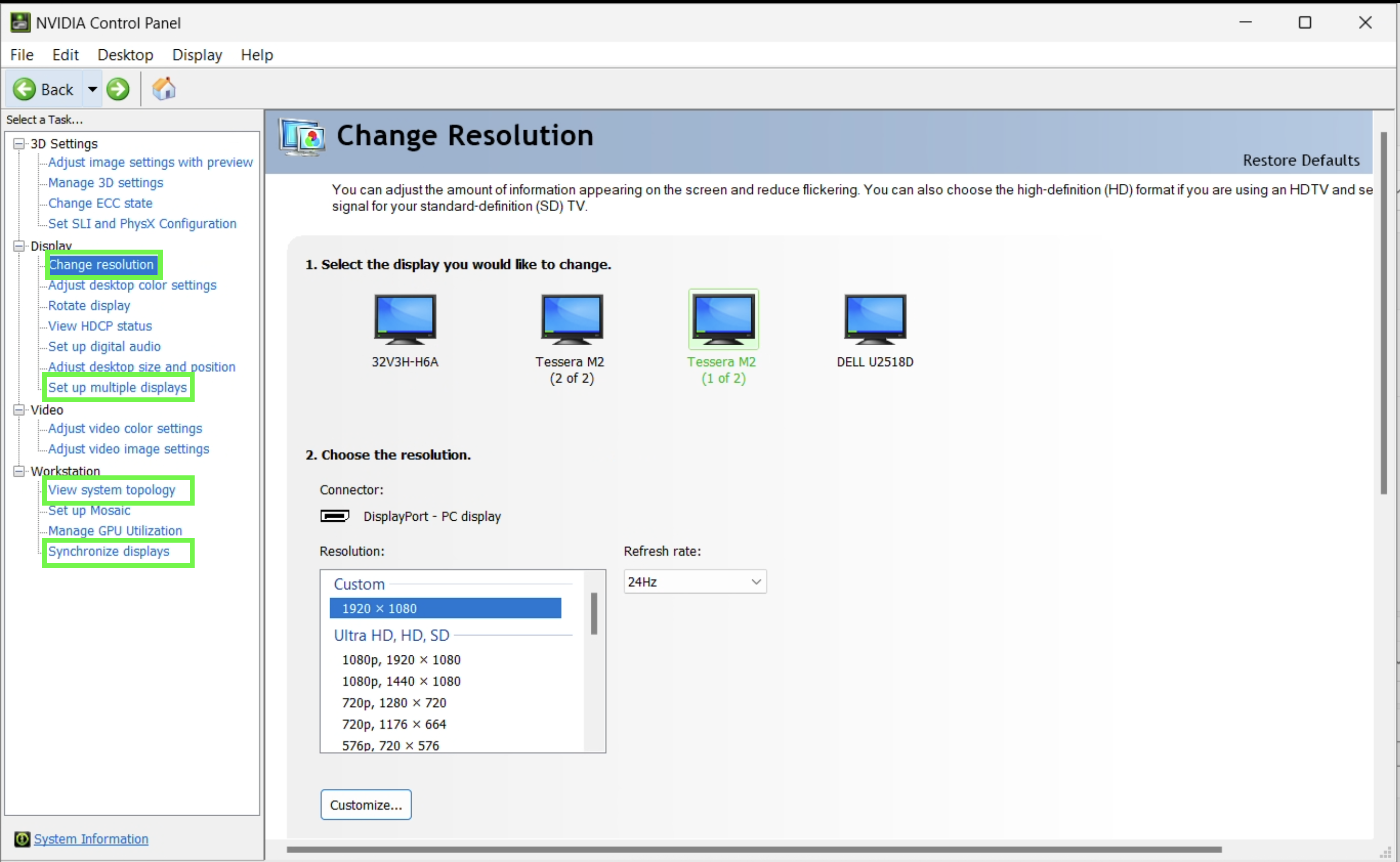
I’ve highlight four places you’ll need to become at least semi-comfortable with to set things up properly.
- Change resolution
- View system topology
- Synchronize displays
and
- Set up multiple displays
which isn’t totally useful but helps you get a birds-eye view of what’s going on.
View system topology
Let’s start a little out-of-order. The View system topology is a good place to start because it shows you the displays and how they are connected and configured.
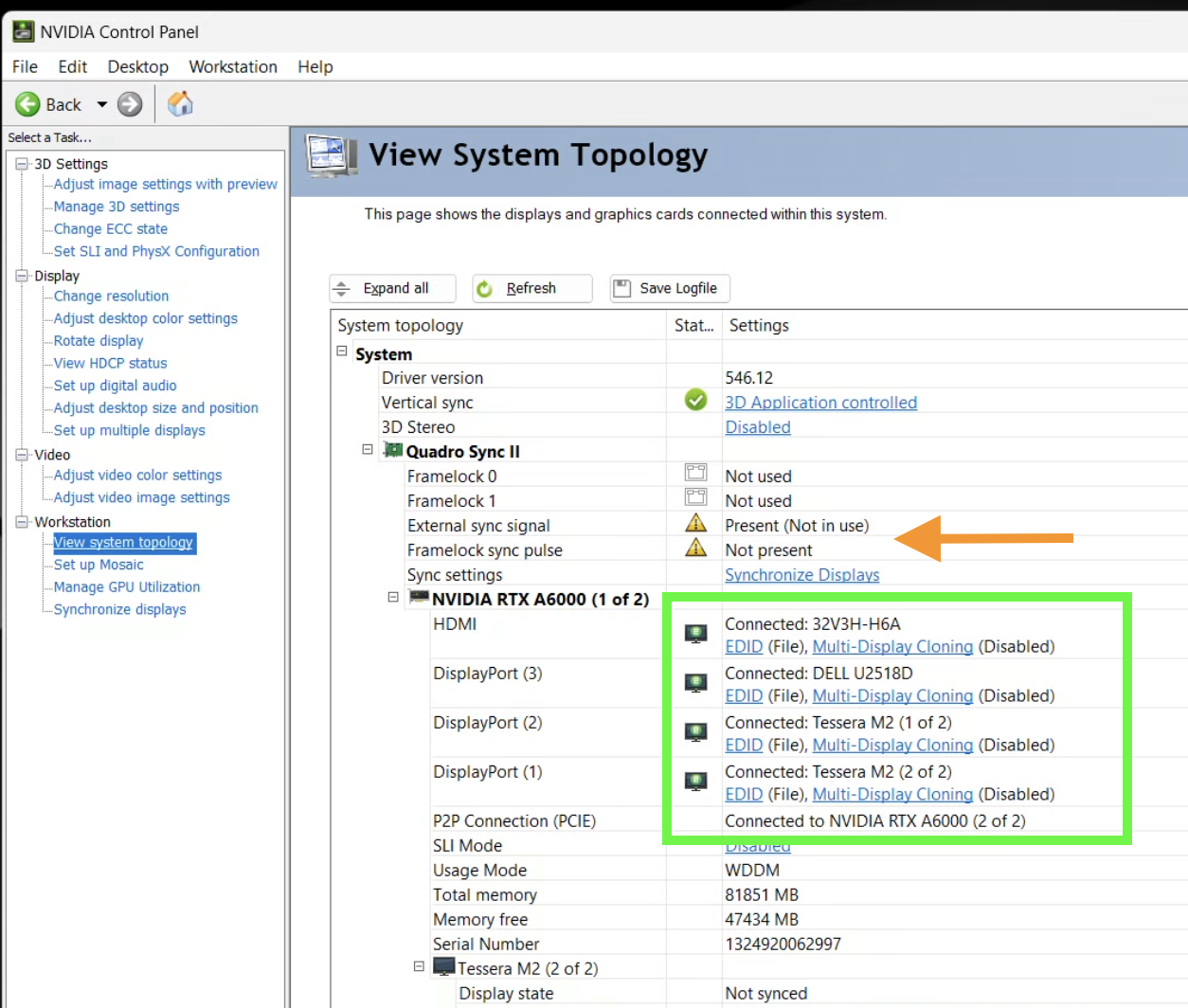
There are a few things to notice in Figure 11. There are four displays listed (Green Box). The two we care about are the Tessera M2 displays. These are the ones that drive the wall. You’ll also see that the EDID (Extended Display Identification Data) is set to File. This is a file that contains explicit display settings for the device. This is important because it’s the file that contains the 24 Hz setting and we’re ‘forcing’ the display to use it.
This has the added benefit that, if someone unplugs the display or turns off the processor it should remember the proper settings when everything is turned back on. So far, this has worked out just fine. Multi-Display Cloning is disabled. You also see that External sync signal and Framelock sync pulse have little warning signs. This is slightly problematic if we want to sync things to the genlock signal, e.g., the cameras. But, it’s not a show stopper frame-rate wise.
Between the green box and orange arrow you see the Synchronize Displays link. We’ll go there later, but for now you can scroll down and see the different settings for the Tessera M2s.
We don’t ‘set’ anything here, but it’s a good reference. Let’s get to the work at hand and get the resolutions and refresh rates where they need to be.
Change resolution
The Change resolution link is where you set the resolution and refresh rate for the displays. Figure 12 shows the settings I saw for the Tessera M2 displays. They are wrong, can you see why?
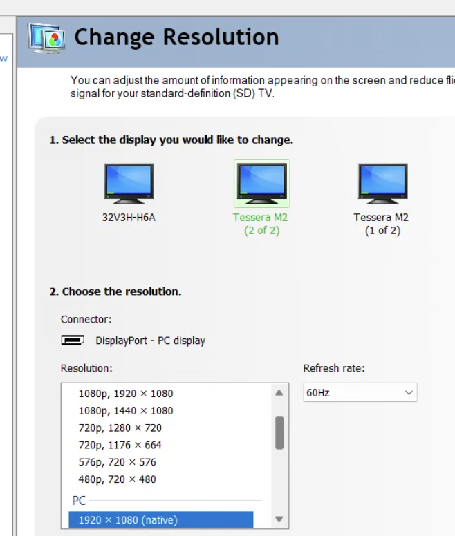
If you scroll to the top of the list of Resolution: you’ll see a Custom section. There should be a 1920x1080 resolution and 24 Hz Refresh rate setting there. Select them for both Tessera M2 displays.9 ]
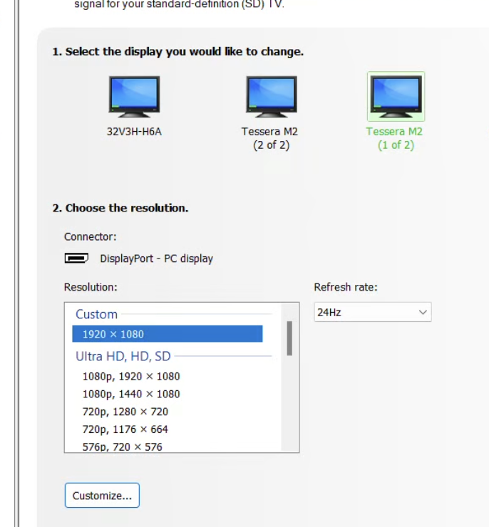
Celebrate with a happy dance and prepare for the next step.
Synchronize displays
There is a ‘feed’ of genlock that comes into the NVIDIA Quadro Sync II card (see Figure 11). This is an ‘external’ sync source (e.g., it’s not coming from the motherboard / computer, but coming from ‘some place else’.). The computer itself can provide synchronization to the displays, but it’s not as good as the genlock signal since that is a ‘master clock’ that all devices can sync to.
The following figure shows the Synchronize Displays link in the NVIDIA Control Panel :
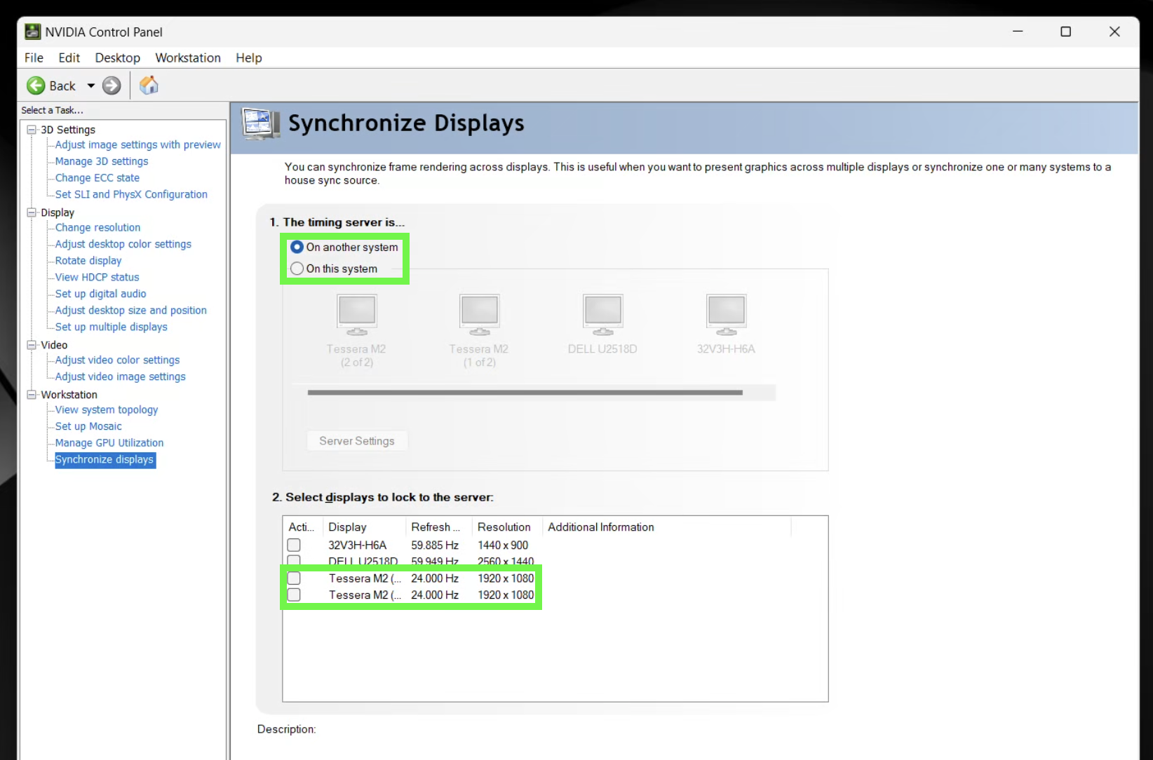
The green boxes show some good news — The bottom box shows us that the Tessera M2 are set to the proper resolution and 24.000 Hz — and some stuff that needs fixed - the timing server isn’t set up properly and there are no Active displays checked.
Even though the Evertz time code / genlock generator is ‘another system’ (It’s its own little box) it is, alas, connected to the Quadro card on this system. So first step is to check that. When we do that, we see a slightly changed display:

Notes from the Future
Note from Aidan
Need to integrate this, just some notes from the last shoot:
Hey! Figured out our issues with wall Little display needed to be set to 1440x900- fixed offset issue Nvidia sync policy in ndisplay goes off of whatever is set as the main display in Windows, so since the little display was set to 60, we always got 60, we can set it to 24, but I don’t think we’ll get house sync without making one of the walls the main display, or seeing if we can change that in the config
Footnotes
For example, it installs its own video driver.↩︎
Aka Perforce or
p4. Perforce is the company, Helix is the product.↩︎Also pre-configured in the template project.↩︎
Note that the card numbers are arbitrary. The point is that a single card delivers the image.↩︎
Note that this is genlock, frame synchronization, and not necessarily a RTC / timecode signal. The Evertz can provide both, but we’re only using the genlock signal right now.↩︎
Again integer 24 fps.↩︎
I need to go back and remember how I did that. It’s not important for setting up the rack for shooting but important for the future times.↩︎
This is the thing I had to create. I’ll have to go back and remember how I did it.↩︎
I am 99% certain that this is the only true place you might need to do this. You’d think Windows would figure this out, but it doesn’t seem to. Especially with Parsec installed and especially with VNC, so we’ll have to play it by ear to see what happens.↩︎